Functional prototypes in production-grade materials
Turn CAD models into accurate metal or plastic prototypes for fit, function and engineering validation. Our rapid CNC prototyping team reviews material, geometry, critical tolerances, finish and inspection needs before machining.
What is CNC rapid prototyping?
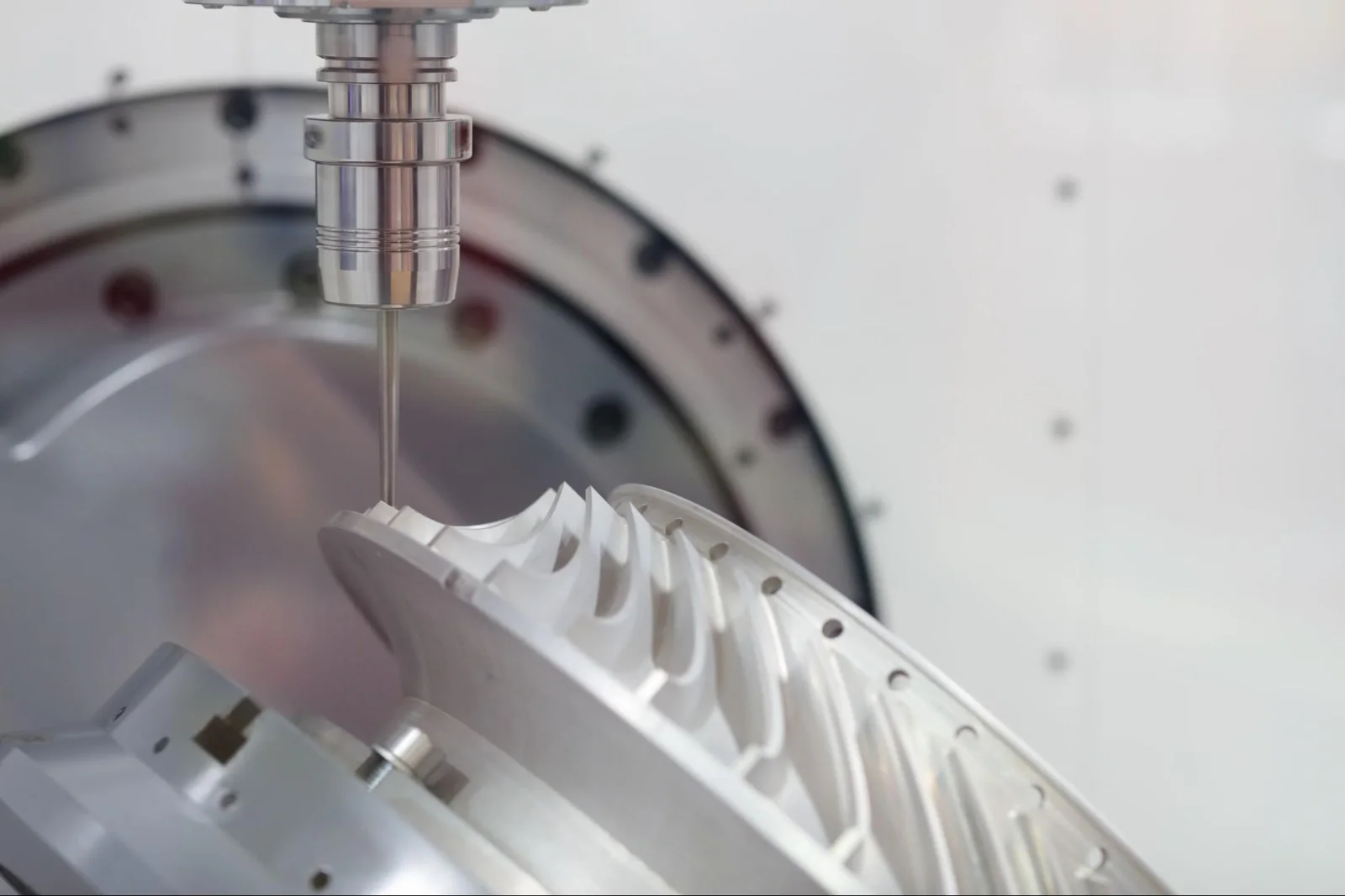
CNC rapid prototyping is a subtractive manufacturing method that machines a prototype directly from solid metal or engineering-plastic stock using a CAD model and CNC toolpaths. It is selected when a development team needs production-like material properties, accurate mating features, threads, sealing faces or a finish that a printed model may not provide.
Because no dedicated mold is required, design revisions can move from updated CAD to a new machined part quickly. This makes rapid prototype CNC machining useful for proof-of-concept builds, functional testing, bridge production and pre-production validation.
How the rapid CNC prototyping process works
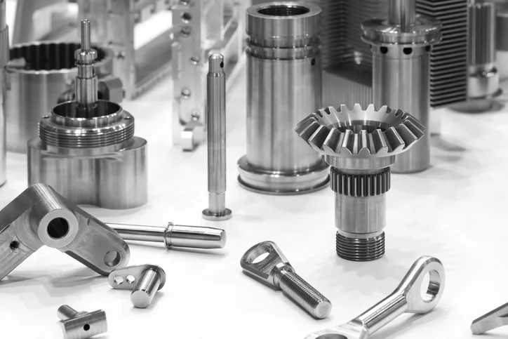
A useful prototype must represent the design intent—not only its outside shape. The workflow below ties CAD, drawing requirements, machining strategy and inspection together.
Send STEP, STP, X_T, IGES or another usable 3D file, plus a 2D drawing for critical dimensions, threads, finishes and datums.
We review access, wall thickness, corner radii, stock, setups, tolerance risk, inspection and requested delivery.
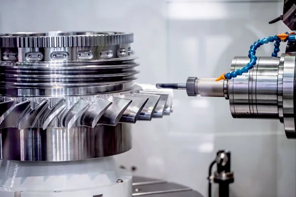
The part is milled or turned from specified stock. Multi-axis setups reduce repositioning where geometry supports it.
Required features are checked, finishing is completed, and parts are cleaned and packed with agreed reports.
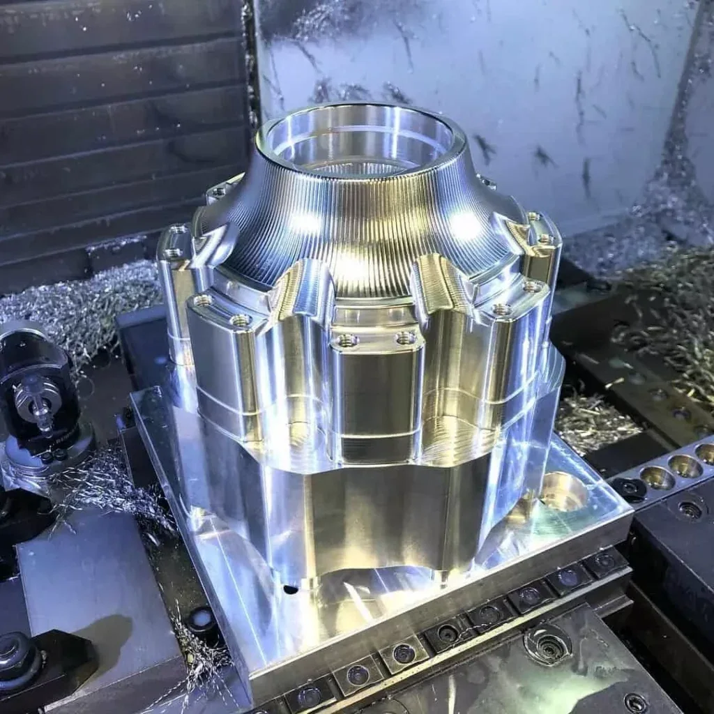
Have a revision ready for machining?
Upload the latest model and drawing so engineering can review feasibility, tolerance and lead time.
CNC machining prototyping capabilities
Process selection depends on the shape, datum strategy, access and quantity—not just the part name.
3-axis CNC milling
Efficient for plates, brackets, housings, pockets, hole patterns and parts with features accessible from several indexed setups.
4- and 5-axis milling
For compound angles, contoured surfaces and multi-face features where fewer re-clamps can improve feature relationships.
CNC turning
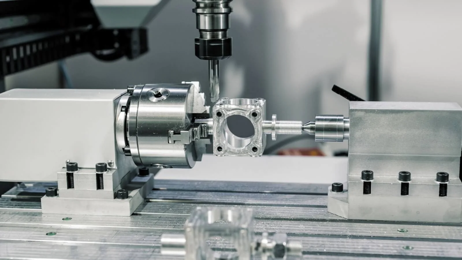
For shafts, bushings, sleeves, threaded components and other primarily rotational prototype geometry.
EDM and secondary work
Applied when narrow slots, sharp internal geometry, hard materials or features inaccessible to conventional cutters require another process.
Unsure which process fits the geometry?
We can compare setup count, achievable features and cost drivers before production.
Metals and plastics for rapid prototyping CNC
Choose the material based on the test objective. If the prototype must predict production behavior, match the intended alloy or polymer grade where practical.
| Material group | Common options | Why engineers choose it | Prototype considerations |
|---|---|---|---|
| Aluminum | 6061-T6, 6082, 7075-T6 | Low mass, good machinability, strength and broad finishing options | Good first choice for functional housings, brackets and fixtures |
| Stainless steel | 303, 304, 316/316L, 17-4PH | Corrosion resistance, strength, heat and hygiene requirements | More machining time than aluminum; grade should match service environment |
| Carbon/alloy steel | 1018, 1045, 4140 and drawing-specified grades | Strength, stiffness, wear performance and cost | Heat treatment and coating can change schedule and dimensions |
| Titanium | Grade 2, Grade 5 | High strength-to-weight ratio, corrosion resistance, biocompatibility use cases | Tooling, heat control and stock availability affect cost and lead time |
| Copper and brass | Copper C110, brass C360 and specified grades | Electrical/thermal performance or low-friction machinability | Pure copper needs stable workholding and suitable tools |
| Engineering plastics | ABS, acrylic, nylon, POM/Delrin, PC, HDPE, PTFE, PEEK | Low mass, insulation, chemical behavior and end-use polymer testing | Moisture, stress, heat, creep and flatness need grade-specific review |
Material availability varies by grade, thickness and requested certification. Substitution is never assumed when the drawing specifies an exact grade.
Tolerances, feature guidance and inspection
| Requirement | Planning guidance | What must be reviewed |
|---|---|---|
| General dimensional tolerance | ±0.005 in (±0.127 mm) is a practical planning value for many machined prototype dimensions | Material, size, geometry, datum structure, wall thickness and measurement method |
| Critical dimensions | Features down to ±0.001 in (±0.025 mm) may be feasible after engineering review | Identify only functional critical features on the 2D drawing; tighter tolerance increases time and inspection cost |
| Threads | Cut or formed internal/external threads; inserts where appropriate | Standard, class, depth, engagement, gauge and insert type |
| Internal corners | Inside radii are required because rotating cutters cannot create a perfectly sharp internal corner | Use the largest acceptable radius and relieve mating corners when needed |
| Thin walls | Keep walls sufficiently rigid for material and geometry; avoid unnecessary depth-to-thickness ratios | Deflection, chatter, heat, clamping and post-machining stability |
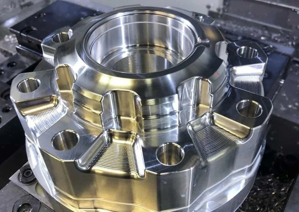
| Surface finish | As-machined surfaces can be supplemented by blasting, anodizing, powder coating, plating or passivation | Masking, cosmetic zones, coating buildup and dimensional allowance |
| Inspection documents | Standard dimensional report, CMM report, material certificate or other agreed records | State report and traceability requirements before quotation |
Important: tolerance is feature-specific. A single blanket tolerance cannot predict capability for every part. Final acceptance criteria must come from the approved drawing and quotation.
Critical fits or sealing surfaces?
Mark them on the 2D drawing so the quote includes the right machining and inspection plan.
Surface finishes for CNC rapid prototypes
Finishing can simulate the production appearance, improve corrosion or wear performance, alter friction, or prepare the prototype for customer demonstration.
- As-machined, deburred and cleaned
- Bead blasting for a uniform matte texture
- Anodizing for eligible aluminum alloys
- Powder coating and wet painting
- Black oxide for suitable ferrous materials
- Passivation, plating, polishing and brushing by specification
Specify color standard, gloss, texture, masking, cosmetic surface class and any dimensions that must be controlled after coating.
CNC prototyping vs 3D printing vs injection molding
| Decision factor | CNC machining | 3D printing | Injection molding |
|---|---|---|---|
| Best fit | Functional, accurate prototypes in production-grade stock | Fast form studies, highly complex internal geometry and early iterations | High-volume production and molded-material/process validation |
| Tooling | No dedicated mold | No dedicated mold | Mold required |
| Material behavior | Properties of wrought/extruded/cast stock selected for the job | Depends on print process, orientation and material system | Representative of molded production material and process |
| Tolerance and finish | Strong choice for interfaces, threads, bores and sealing features | Process-dependent; secondary machining may be needed | Repeatable after mold and process are validated |
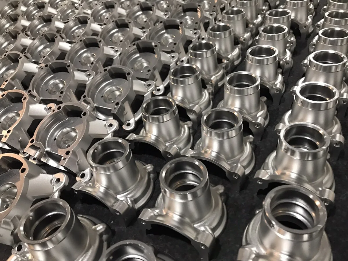
| Quantity economics | Prototypes and low-volume bridge quantities | Very low quantities and complex shapes | Higher quantities that justify tooling |
| Main constraint | Tool access, internal radii, setup count and material removal | Layer/process limitations and anisotropy | Tooling cost, design lock-in and longer launch preparation |
A hybrid route is common: print an early shape model, machine functional validation parts, then move to tooling after the design stabilizes.
Where CNC rapid prototypes are used
Aerospace and UAV
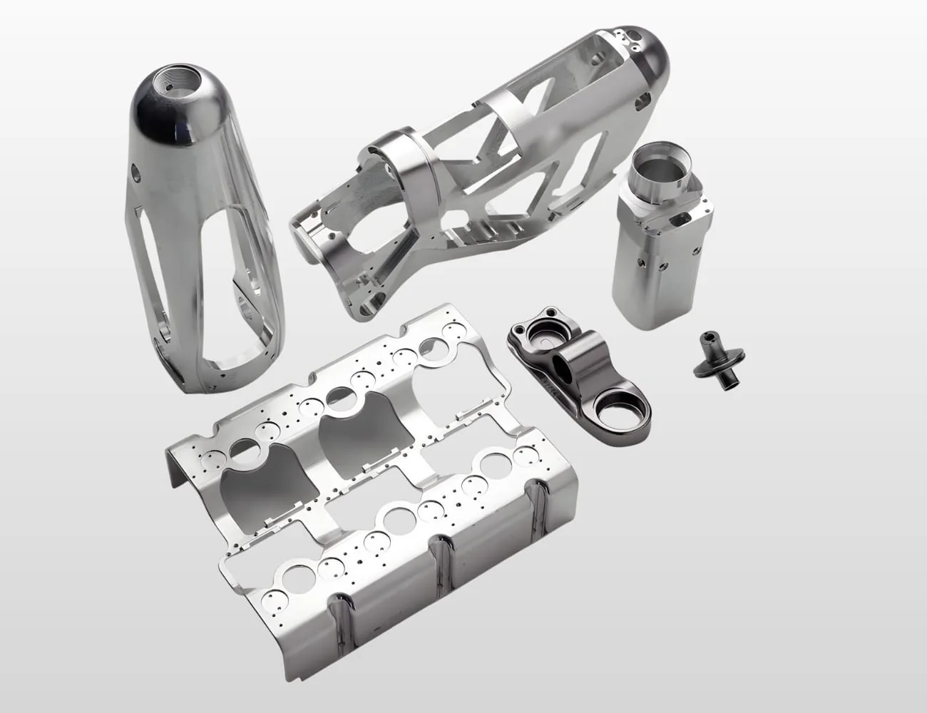
Lightweight brackets, sensor housings, test fixtures, duct interfaces and structural proof parts where traceable material and feature relationships matter.
Medical and laboratory equipment
Instrument housings, positioning components, test rigs and development hardware produced to drawing-defined materials and inspection requirements.
Automotive and mobility
Powertrain interfaces, fluid-system components, mounts, fixtures and pre-production parts for fit, thermal and functional testing.
Robotics and automation
End-effectors, motor mounts, bearing housings, linkages, gripper parts and machine-vision brackets.
Electronics
Heat sinks, RF housings, protective enclosures, connector interfaces and precision frames.
Industrial equipment
Wear parts, manifolds, valves, gauges, replacement components and assembly fixtures for design verification or bridge supply.
Need one prototype or a small validation batch?
Tell us the test purpose and quantity so the manufacturing plan matches the decision you need to make.
DFM checklist for a faster CNC rapid prototype
Define the test objective
State whether the part is for appearance, assembly fit, pressure, load, thermal, wear or regulatory testing. This helps prioritize tolerances and material.
Separate critical from noncritical
Use the 2D drawing to identify datums, fits, threads, sealing faces and functional GD&T. Avoid tightening every dimension by default.
Design for cutter access
Use generous internal radii, avoid unnecessary deep narrow pockets and consider reliefs where a mating square corner is required.
Control thin and tall features
Thin walls and slender bosses can deflect. Add support, shorten unsupported height or allow a practical wall thickness where function permits.
Standardize holes and threads
Prefer standard drill and thread sizes, give realistic depths and show whether inserts or thread gauges are required.
Plan finish and inspection early
Coating thickness, masking and cosmetic requirements affect dimensions, handling, schedule and quotation.
Lead time and pricing factors
Typical planning range: straightforward prototype work can start from approximately 3–5 business days after the manufacturable files, material, quantity, finish and inspection requirements are confirmed. Complex parts, special stock, heat treatment, finishing or detailed reporting take longer.
Price is driven by material and stock size, programming, setup count, cutting time, tool access, tolerance, finish, inspection and quantity. A part designed for fewer setups with clearly limited critical tolerances is usually faster and more economical.
What to send—and what to verify before ordering
Quote package
- 3D CAD model and revision level
- 2D drawing with datums, tolerances, threads and critical features
- Material grade and acceptable certification
- Prototype quantity and expected follow-on volume
- Finish, masking and cosmetic requirements
- Inspection report, CMM, gauge or traceability needs
- Required delivery date and destination
Supplier questions
- Can the supplier explain tolerance risks before machining?
- Are material, finish and inspection included in the quotation?
- How will revisions and nonconformities be controlled?
- Which dimensions will be reported and by what method?
- Can the same source support pilot and bridge quantities?
- Is the promised lead time based on confirmed stock and finishing?
Ready for a drawing-specific review?
Include the model, drawing, material, quantity, finish and required date for a useful response.
Frequently asked questions
What is the typical lead time for CNC rapid prototyping?
For straightforward parts, lead time can start from about 3–5 business days after CAD, drawing, material, quantity, finish and inspection requirements are confirmed. Complexity, special stock, secondary processing and documentation can extend the schedule.
What tolerance can a CNC rapid prototype hold?
±0.005 in (±0.127 mm) is a practical general planning value for many machined features. Critical dimensions down to ±0.001 in (±0.025 mm) may be feasible after reviewing material, geometry, datums, wall thickness and inspection method. The approved drawing governs acceptance.
Is CNC prototyping better than 3D printing?
Neither process is universally better. CNC is often preferred for production-grade material properties, precise mating features, threads and machined finishes. 3D printing can be faster or less expensive for early form studies and geometry that cutting tools cannot access.
Which files should I send for a quote?
Send a 3D CAD file and a controlled 2D drawing. Include material grade, quantity, finish, critical dimensions, threads, cosmetic requirements, inspection documents and delivery destination.
Can CNC rapid prototyping produce both metal and plastic parts?
Yes. Common choices include aluminum, stainless steel, alloy steel, titanium, brass, copper and engineering plastics such as ABS, acrylic, nylon, POM/Delrin, polycarbonate, HDPE, PTFE and PEEK, subject to grade and stock availability.
Can prototype machining continue into low-volume production?
Yes. CNC is frequently used for pilot, bridge and low-volume production. The team should review repeatability, fixture strategy, inspection frequency, material procurement and whether another process becomes more economical as volume rises.
How can I reduce CNC prototype cost?
Use standard stock and threads, increase internal radii, avoid very deep narrow pockets, limit tight tolerances to functional features, reduce setup count, and specify only the inspection and finish the test actually requires.
Related capabilities: CNC machining services, CNC milling, CNC turning, 3D printing, aluminum machining and titanium machining.
Start your CNC rapid prototype with a clear manufacturing plan
Upload the latest CAD and drawing. We will review material, machinability, critical tolerances, inspection, finish, quantity and a realistic delivery plan before production.